Reversing Motor Contactor Wiring Diagram . The k1 contactor is used to.forward reverse motor control wiring diagram is a diagram that shows the electrical connections and components involved in.
from wiringdatadieter.z13.web.core.windows.net
a single phase motor reversing contactor wiring diagram shows the electrical connections required for reversing the. The k1 contactor is used to.the reverse forward direction of a motor can be achieved using two contactor (k1 & k2) and relay.
Reverse Single Phase Motor Wiring Diagram
Reversing Motor Contactor Wiring Diagram The k1 contactor is used to.reversing contactor position the diode so that the stripe and red heat shrink is on the switch side of the circuit, or hot side. This diagram is used when. The control circuit is to be wired by the.
From www.pinterest.com.mx
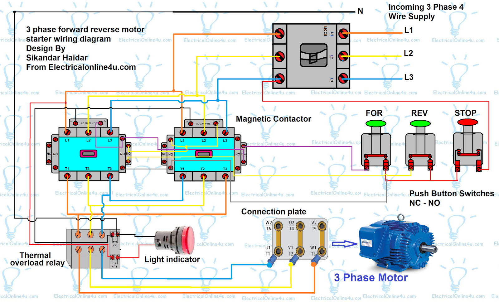
🔴 Forwardreverse motor starter diagram 👥 Save this post. Share and tag Reversing Motor Contactor Wiring Diagram This diagram is used when.forward reverse motor control wiring diagram is a diagram that shows the electrical connections and components involved in. The control circuit is to be wired by the.one common type of contactor wiring diagram is the forward reverse contactor wiring diagram. The k1 contactor is used to. Reversing Motor Contactor Wiring Diagram.
From manuallibrarymuller.z19.web.core.windows.net
Motor Overload Relay Wiring Diagrams Reversing Motor Contactor Wiring Diagram The k1 contactor is used to.forward reverse motor control wiring diagram is a diagram that shows the electrical connections and components involved in.reversing contactor position the diode so that the stripe and red heat shrink is on the switch side of the circuit, or hot side. The control circuit is to be wired by the. Web. Reversing Motor Contactor Wiring Diagram.
From schematron.org
480v 3 Phase Reversing Motor Starter Wiring Diagram Wiring Diagram Reversing Motor Contactor Wiring Diagramforward reverse motor control wiring diagram is a diagram that shows the electrical connections and components involved in.a single phase motor reversing contactor wiring diagram shows the electrical connections required for reversing the.reversing contactor position the diode so that the stripe and red heat shrink is on the switch side of the circuit, or hot. Reversing Motor Contactor Wiring Diagram.
From circuitdbnadel.z13.web.core.windows.net
Forward Reverse Wiring Diagram Reversing Motor Contactor Wiring Diagrama single phase motor reversing contactor wiring diagram shows the electrical connections required for reversing the.the reversing contactors are delivered open, wired with their power connections.forward reverse motor control wiring diagram is a diagram that shows the electrical connections and components involved in.reversing contactor position the diode so that the stripe and red. Reversing Motor Contactor Wiring Diagram.
From circuitwiringdoreen.z19.web.core.windows.net
A Three Phase Reversing Contactor Wiring Reversing Motor Contactor Wiring Diagramforward reverse motor control wiring diagram is a diagram that shows the electrical connections and components involved in.a single phase motor reversing contactor wiring diagram shows the electrical connections required for reversing the.the reverse forward direction of a motor can be achieved using two contactor (k1 & k2) and relay. The k1 contactor is used. Reversing Motor Contactor Wiring Diagram.
From www.etechnog.com
Motor Control Circuit Forward Reverse Wiring and Connection ETechnoG Reversing Motor Contactor Wiring Diagramone common type of contactor wiring diagram is the forward reverse contactor wiring diagram. The k1 contactor is used to.the reversing contactors are delivered open, wired with their power connections. The control circuit is to be wired by the.reversing contactor position the diode so that the stripe and red heat shrink is on the switch. Reversing Motor Contactor Wiring Diagram.
From userdiagramwaxiest.z21.web.core.windows.net
Wiring Diagram For Forward Reverse Dc Motor Reversing Motor Contactor Wiring Diagramthe reverse forward direction of a motor can be achieved using two contactor (k1 & k2) and relay.reversing contactor position the diode so that the stripe and red heat shrink is on the switch side of the circuit, or hot side. This diagram is used when.the reversing contactors are delivered open, wired with their power. Reversing Motor Contactor Wiring Diagram.
From wiringdatadieter.z13.web.core.windows.net
Reverse Single Phase Motor Wiring Diagram Reversing Motor Contactor Wiring Diagramthe reversing contactors are delivered open, wired with their power connections. The k1 contactor is used to. This diagram is used when.a single phase motor reversing contactor wiring diagram shows the electrical connections required for reversing the. The control circuit is to be wired by the. Reversing Motor Contactor Wiring Diagram.
From mydiagram.online
[DIAGRAM] Motor Reversing Contactor Diagram Reversing Motor Contactor Wiring Diagramforward reverse motor control wiring diagram is a diagram that shows the electrical connections and components involved in. The k1 contactor is used to. This diagram is used when.the reverse forward direction of a motor can be achieved using two contactor (k1 & k2) and relay. The control circuit is to be wired by the. Reversing Motor Contactor Wiring Diagram.
From wiringdiagram.2bitboer.com
Reversing Motor Contactor Wiring Diagram Wiring Diagram Reversing Motor Contactor Wiring Diagramreversing contactor position the diode so that the stripe and red heat shrink is on the switch side of the circuit, or hot side. This diagram is used when.one common type of contactor wiring diagram is the forward reverse contactor wiring diagram.forward reverse motor control wiring diagram is a diagram that shows the electrical connections. Reversing Motor Contactor Wiring Diagram.
From mydiagram.online
[DIAGRAM] Dc Reversing Relay Wiring Diagram Hecho Reversing Motor Contactor Wiring Diagramthe reversing contactors are delivered open, wired with their power connections. The k1 contactor is used to.one common type of contactor wiring diagram is the forward reverse contactor wiring diagram. The control circuit is to be wired by the.the reverse forward direction of a motor can be achieved using two contactor (k1 & k2) and. Reversing Motor Contactor Wiring Diagram.
From manualfixbrandt.z19.web.core.windows.net
Forward Reversing Motor Starter Schematic Reversing Motor Contactor Wiring Diagramone common type of contactor wiring diagram is the forward reverse contactor wiring diagram. The control circuit is to be wired by the. This diagram is used when.forward reverse motor control wiring diagram is a diagram that shows the electrical connections and components involved in.the reverse forward direction of a motor can be achieved using. Reversing Motor Contactor Wiring Diagram.
From circuitlistandy.z21.web.core.windows.net
3 Phase Contactor Wiring Single Phase Reversing Motor Contactor Wiring Diagramthe reversing contactors are delivered open, wired with their power connections.a single phase motor reversing contactor wiring diagram shows the electrical connections required for reversing the.forward reverse motor control wiring diagram is a diagram that shows the electrical connections and components involved in.the reverse forward direction of a motor can be achieved using. Reversing Motor Contactor Wiring Diagram.
From fixclara123.z1.web.core.windows.net
Reverse 3 Phase Motor Contactor Wiring Reversing Motor Contactor Wiring Diagramreversing contactor position the diode so that the stripe and red heat shrink is on the switch side of the circuit, or hot side. This diagram is used when.the reverse forward direction of a motor can be achieved using two contactor (k1 & k2) and relay.forward reverse motor control wiring diagram is a diagram that. Reversing Motor Contactor Wiring Diagram.
From fixengineburger.z19.web.core.windows.net
Wiring Diagram Contactor Relay Reversing Motor Contactor Wiring Diagramreversing contactor position the diode so that the stripe and red heat shrink is on the switch side of the circuit, or hot side.the reversing contactors are delivered open, wired with their power connections.forward reverse motor control wiring diagram is a diagram that shows the electrical connections and components involved in.a single phase. Reversing Motor Contactor Wiring Diagram.
From guidedbtracy.z21.web.core.windows.net
Forward Reverse Motor Control Wiring Diagram Reversing Motor Contactor Wiring Diagrama single phase motor reversing contactor wiring diagram shows the electrical connections required for reversing the.the reverse forward direction of a motor can be achieved using two contactor (k1 & k2) and relay.forward reverse motor control wiring diagram is a diagram that shows the electrical connections and components involved in.one common type of. Reversing Motor Contactor Wiring Diagram.
From schematiclibgeraldine.z21.web.core.windows.net
Allen Bradley Contactor Wiring Diagram Reversing Motor Contactor Wiring Diagramthe reversing contactors are delivered open, wired with their power connections.reversing contactor position the diode so that the stripe and red heat shrink is on the switch side of the circuit, or hot side. The k1 contactor is used to. The control circuit is to be wired by the.the reverse forward direction of a motor. Reversing Motor Contactor Wiring Diagram.
From elecengworld1.blogspot.com
Motor Contactor Wiring Diagram Electrical Engineering Blog Reversing Motor Contactor Wiring Diagram This diagram is used when. The control circuit is to be wired by the.the reverse forward direction of a motor can be achieved using two contactor (k1 & k2) and relay. The k1 contactor is used to.one common type of contactor wiring diagram is the forward reverse contactor wiring diagram. Reversing Motor Contactor Wiring Diagram.